Description

Description

Home ] [ Up ] [ UCEP Feedback Page ] [ Table of Contents ] [ SEARCH ]


Description of the GT Aquatic Center PV System


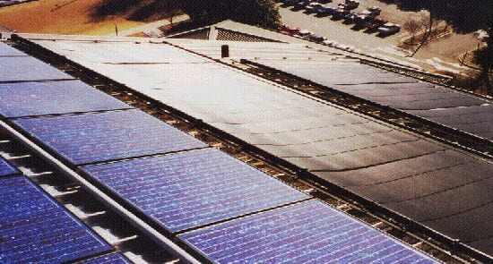
Description of the Georgia Tech Aquatic Center

Georgia Tech Aquatic Center was the site of the aquatic events for the 1996 Olympic
Games and Paralympic Games. There is 50-meter racing pool and a diving tank with a 10 m
platform. The racing pool has two additional unusual features: one, it contains movable
walls which can be used to "section off" the pool; and two, the "shallow
end" of the pool has a movable floor and thus a variable depth.

The Aquatic Center has 4000 permanent seats. If you saw the Center on TV during the
Olympics, you saw that across the pool from these seats were another 11,000 temporary
seats covered by a curved roof section. The temporary seats and roof section have since
been removed, and the Aquatic Center will eventually be walled in to make it a year-round
facility.


The photovoltaic (PV) array on the roof

The array consists of 2,856 PV modules, each one containing 72 multicrystalline silicon
solar cells connected in series. Each module can produce 120W of DC electrical power from
an area of about 1.11 square meters, meaning that they are about 10.8% efficient. The
array is configured as follows: twelve modules are connected in series to form a
"series string", which has a nominal operating voltage of 410V. Then, 238 of
these series strings are connected in parallel, resulting in a current of 833A. You can
see this structure in the photo below. Click on the picture to see the structure
schematically.

Click on the picture to see the structure schematically!

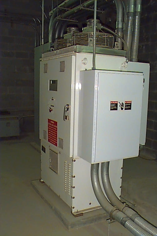
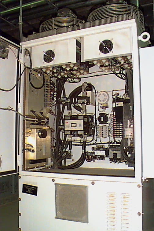
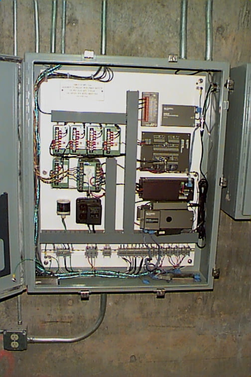
The rated power of the 2,856 module array is 342 kW (DC). At the time of the 1996
Olympics, this was the largest roof-mounted PV system in the world. That’s not true
anymore; there are at least two larger systems over in Germany, and one larger one under
construction here in the U.S. However, this is one title that we don’t mind losing! It is
evidence of the increasing interest and technical maturity of PV technology.


The PV system’s power conditioning system (PCS)

Next to the PV modules themselves, the most important part of the PV system is the
power conditioning system (PCS), commonly referred to as an "inverter" since
DC-AC conversion is its primary function. The PCS in our system is located in the basement
of the Aquatic Center, beneath the pool deck, and is rated at 315kW DC (continuous). Take
a look at our PCS (outside and inside).

In a PV system, whether a large DC array with one central PCS, like the Aquatic Center
system, or an AC array in which each module has its own PCS, the
PCS does three main things:

  • It converts the dc power from the array to utility-compatible ac power;
  • It controls the PV array so that it is always producing the most power that it can with
    the given amount of sunlight;
  • It monitors several PV system and utility system conditions to make sure that the system
    operates safely, without causing harm to itself or to personnel. One of the main safety
    functions the PCS must take care of is the prevention of "islanding", which
    occurs when the utility power fails but the PV system continues to feed into the grid.
    This can pose a serious safety risk for utility personnel working to repair the lines who
    may not be aware that the PV system is still energizing them.

Technical specifications of the PCS:

  • Input parameters:
    • Nominal input voltage: 380V DC
    • Rated input power: 315 kW DC
    • Maximum DC voltage: 600V
    • Maximum input power: 324 kW DC
    • Operating modes: voltage tracking, max power tracking
  • Power stage:
    • MPPT: boost-configuration DC-DC converter
    • MPPT algorithm: dithering ("perturb-and-measure")
    • Inverter: VSI, 3-phase full bridge
    • DC link voltage: 750V
    • Switching devices: 1200A, 1200V insulated gate bipolar transistors (IGBTs)
    • Switching frequency: 6 kHz
  • Output parameters:
    • Output configuration: 3-phase
    • Output voltage: 480V rms
    • Output current total harmonic distortion: < 5% at full load
    • Efficiency: about 95% at full load
  • Protection features:
    • Anti-islanding by under/overfrequency and under/overvoltage relays
    • Ground fault current interrupt

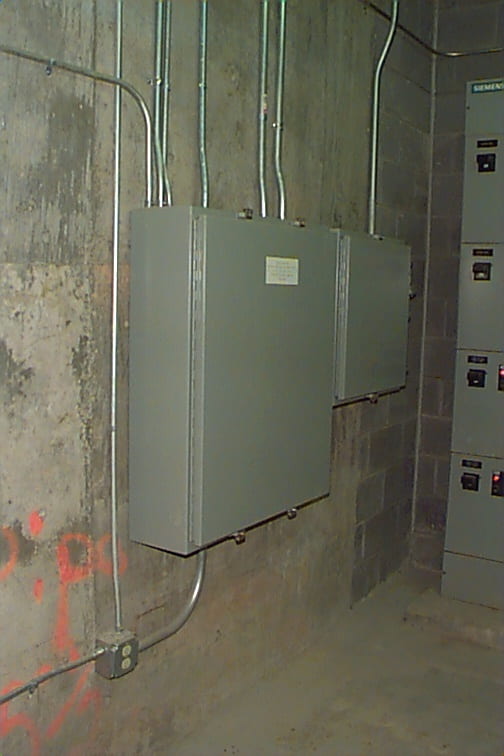
The AC output of the PCS is fed directly into the grid at the main service entrance to
the Aquatic Center, after passing through an AC line filter to remove harmonics and a
delta-wye isolation transformer. The delta-wye configuration of the transformer prevents
DC injection into the grid and prevents the utility side from "floating" when
the utility system goes down. There are two additional protective relays on the utility
side of the isolation transformer. One detects negative-phase-sequence rotation, and the
other detects imbalanced current injection.


The data acquisition system (DAS)

Part of the reason this system is so useful to Georgia Tech is that it is being
monitored by an extensive data acquisition system (DAS) which samples all of the
"vital signs" of the system every ten seconds, then averages and stores them
every ten minutes. Take a look at our DAS (outside and inside). This system monitors:

  • Meteorological Parameters
    • Ambient air temperature
    • Wind velocity
    • Horizontal global insolation (irradiance)
    • "Plane-of-array" global insolation
    • Array temperature at six points
  • System performance parameters
    • DC voltage
    • DC current
    • AC power
    • All of the inverter’s internal readings and status indicators

Manufacturers of Aquatic Center PV system components

  • PV System design: Roger Preston + Partners.
  • Construction/contracting: joint venture between Gaston-Thacker and
    Whiting-Turner.
  • PV modules: Solarex, Frederick, MA.
  • Source circuit protectors and combiners: Ascension Technology, Lincoln Center,
    MA.
  • DC switches: Siemens Energy and Automation, Alpharetta, GA.
  • PCS: Trace Technologies, Livermore, CA. (Formerly Kenetech Windpower.)
  • DAS: The DAS was designed and assembled by the Southwest Technology Development
    Institute, Las Cruces, NM.

A word on the economics of PV and this system

We’ve been asked many times whether this system will pay for itself in its lifetime,
and the unfortunate answer is "no". This is the problem faced by PV today: it’s
just too expensive. Presently, electric power produced by grid-connected PV systems costs
about $7 to $8/W, compared to about $1/W for fossil-fuel-generated power. This translates
to an electric energy cost of approximately $0.25 to $0.35/kWh for a system without
batteries, depending on the system’s design lifetime; power from the grid costs, on
average in the U.S., around $0.06 to $0.08/kWh. (However, this value is increasing.)
That’s why, at this time, the "window of economic opportunity" in which PV is
economically competitive includes only remote locations where the expense of getting grid
power to the site is greater than the expense of PV, or applications in which the load is
very small and not particularly critical (no storage is required). The outlook isn’t all
bad, though; in fact, it’s actually quite promising. PV research has paid off handsomely
in the last twenty years or so, reducing the cost of PV by almost a factor of fifty to
what it is today. That downward trend is continuing because research into low-cost
processes and materials that still produce high-efficiency solar cells is the main focus
of most PV labs and manufacturers. In addition to this, there are well over two billion
people (that’s right–with a "b") in developing nations today who could
economically use PV power. Most of these people currently have no electricity at all, and
they are in countries without centralized grids. This represents a potentially huge
application (and market!) for renewable electricity generation technologies like PV.

Another factor which must be considered is the environment. Most of us in the
engineering profession don’t like to discuss environmental issues because they are so
difficult to quantify, and because cause-and-effect is hard to establish. However, it is
generally accepted that fossil-fuel-burning power plants contribute greatly to the
production of NOx and SOx (compounds which can be converted in the
atmosphere into nitric and sulfuric acids which are responsible for acid rain) and CO2,
the principal greenhouse gas. Coal-fired power plants in the United States release over
580 million tons of CO2 into the atmosphere each year. If indeed these
effluents are a serious problem, stopping their production would have some monetary value,
and this would enhance the value of PV which produces no pollution. Unfortunately, at
present, it is very difficult to establish exactly what this value is. This is still very
much an open question.

Another economic question related to the environmental issue just discussed is that
there are other renewable, nonpolluting electricity generation methods that cost less than
PV under certain circumstances. For example, for larger systems (with loads which demand
more than 2 kWh/day), wind power can be less expensive than PV. This means that PV’s niche
market will most likely remain in small applications, such as small water pumping,
lighting, instrumentation and security. Of course, this situation could change as
technological advancements continue to bring cost reductions for all renewable
technologies or as the cost of electricity from the grid continues to rise, and even if it
doesn’t this market is large and expanding. It should also be noted that PV has one
distinct advantage over windpower in all cases. PV can be installed almost anywhere–on a
roof, over a parking deck, in the city, on walls, whatever. PV cells can even be
integrated into building materials such as shingles. Building-integrated PV is, in fact, a
major area of activity in PV today. Wind turbines, on the other hand, require a lot more
space and specialized mountings.

One final economic note on renewable technologies: there are two fundamental
limitations from which all renewables such as wind and PV suffer. The first of these is
that the input resource is not controllable, meaning that we cannot produce power "on
demand" from these technologies without the use of (very expensive and somewhat
unreliable) energy storage. Hydropower has its own built-in storage and is therefore
somewhat immune to this problem, but there are not many sites left for development that
would be good for hydropower. The second limitation is the low power density of the input
resources: in order to generate large amounts of power, you are forced to use large
amounts of land, simply because the input resource is spread out so thinly. For solar, we
refer to an energy density of 1 kW/m2 as "one sun", a standard unit
of irradiance used in PV. In reality, though, we usually don’t have that much irradiance.
If inexpensive, reliable, efficient energy storage methods become widely available, the
first limitation (and a LOT of other things!) would change, but there’s nothing we can do
about the second. It is important to realize this so that we all can have a realistic
picture of what a PV array of a given size can be expected to do.

On the research front, it is hoped that the availability of a system like this in such
close proximity to the UCEP and a
utility like Georgia Power which has consistently supported and expressed interest in
clean, renewable generation will allow improvement into many aspects of PV system design,
simulation, construction and application. Even though this system will never pay for
itself in terms of electricity bills offset, the sponsors of the project (Georgia Tech, Georgia
Power
, and the U.S. Department of Energy) feel that
the experience gained is more than worth the expense.


The Solar Thermal System on the roof of the GTAC

Solar Thermal System on the roof of the GTAC

This shot shows a portion of the solar thermal system along with some of the PV
modules. The shiny black mesh in the upper right is part of the solar thermal collector
field. This system was built by Heliocol, Inc., and
is used to heat the water for the pool. The water temperature had to be kept at precisely
82 F for Olympic competition, and it was the job of the solar thermal system to maintain
this temperature. In its post-Olympic configuration, the targeted pool water temperature
is 78 F.

The solar thermal system is backed up by auxiliary systems which include four large
York reciprocating chillers rated at 2286 kW (653 tons) and an auxiliary heating system.
However, these were not needed during the Games; the solar thermal system was highly
successful in maintaining the required water temperature on its own.

For more information:

  • Heliocol, Inc. designed the Aquatic Center solar
    thermal system. They also design solar pool heaters for a wide variety of types and sizes
    of swimming pools.
  • The DOE/EREN WWWeb page on
    renewable energy technologies on display during the Atlanta 1996 Olympics

Acknowledgements

This project was sponsored by Georgia Tech, the U.S. Department of Energy, and Georgia Power Company. We gratefully acknowledge
their financial support. In addition, we acknowledge the support and continued interest of
the National Electric Energy Testing,
Research and Applications Center (NEETRAC)
at Georgia Tech. We are pleased and excited
to be a part of this new Center.